Make a Machine
Table of content:
1 - Designing1.1 - Day 1
1.2 - Day 2
1.3 - Day 3
1.4 - Day 4
1.5 - Day 5
1.6 - Day 6
1.7 - Day 7
1.7.1 - Manual Actuation 1.7.2 - Automatic Actuation
1.8 - Day 9 | Final result
2 - Assembling
3 - Group Webpage Link
In this week we had to make a machine while working in a group. The purpose was to make such a machine where there is use of several
mechanical parts like bearings, timing belt, pulley, gears, aluminium extrusions, nut-bolts, guide rails and electronics parts like stepper
motor, servo motor, motor drivers, shield for the motors, micorcontroller
![]()
so that we can get to know about their principles and how it works
and with that knowledge we can make any machine of different mechanism in the future.
After some discussion, it was decided to make a conductive ink printing machine. So there were major two task, building the machine and making
the conductive ink. Conductive ink means an ink through which we can pass the electricity. With this we can print circuits and then attach the
components onto the ink traces and use it as a large size PCB which will help the children to understand about circuit more easily.
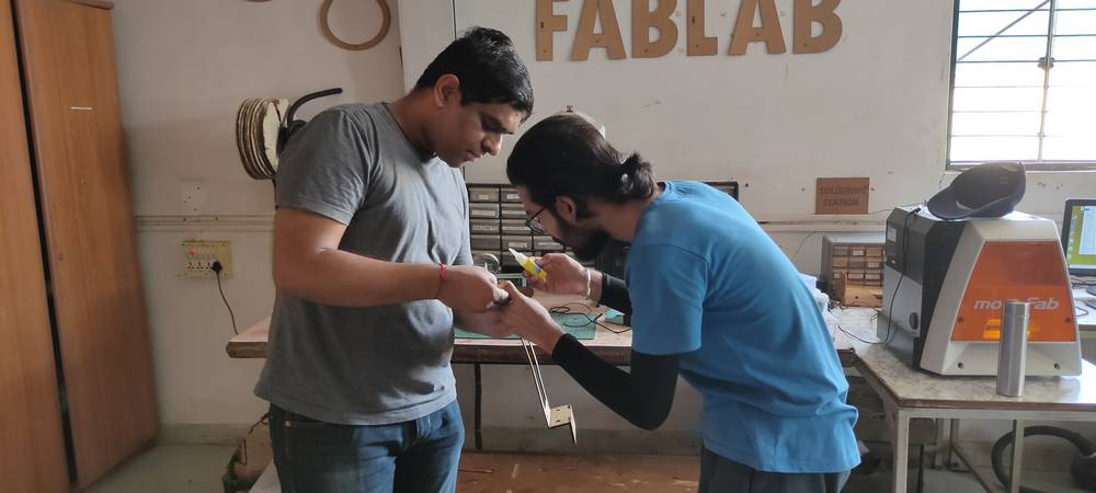
To make the conductive ink, Kiran Wakchaure used ingredients like charcol, fevicol, water, lemon, salt and water
and after miximg them well till the texture looks like a liquid paste we tested the conductivity of the ink,
After some discussion, we decided to build the machine with CoreXY mechanism.
Reference link for CoreXY mechanism: http://corexy.com/
CoreXY mechanism basically is the movement of X and Y axis with the help of two stepper motor, 10 pulley(two pulley needs to be mounted onto
the stepper motor and rest 8 are idle pulley) and two set of timing belt. One timing belt needs to be on one height entwined around fIve pulley
(one of which is mounted onto the motor and rest 4 idle pulley) and the rest 5 pulley and timing belt needs to be on another height. Diagram for
the CoreXY mechanism: http://corexy.com/reference.png
You'll find detailed description about the CoreXY mechanism and its videos from their website.
Designing
Different task were assigned to everywone for building the machine. Between me and Kishore Gaikwad we had the responsibility to design the Gantry of the CoreXY mechanism. Devesh Nair and Vrushabh Zunhunkar had the responsibility to operate the three motors(two for X and Y mechanism and one for the extrusion of ink) and configure it with Marlin so that the printer prints the design with the ink accordiung to the size of our machine and also to figure out how to convert our design into gcode and upload it to the microcontroller. Kiran Wakchaure had the responsibility to design the extruder and make the conductive ink. Jaydeep Parejiya had taken the responsibility of all the fabrication like laser cutting and 3D printing. Ashish Shende was majorly helping us with the assembly and making the conductive ink. It was decided that after everything is prepared, everyone will participate in the assembling of the machine.As mentioned above, I and Kishore Gaikwad had the responsibility to make the design of the gantry. The reason why i am saying gantry and not including the design of the frame is because we already had aluminium extrusion in our inventory. We had to use 4 piece of 20x20x200, 20x20x320 and 20x20x400 aluminuim extrusion to make the frame.
In fact apart from purchasing linear bearing, pulley, timing belt and some bolts and nuts, we didn't need to purchase anything. We already had aluminium extrudionns, guide rails, aluminium plate for bed, stepper motors, RAMPS 1.4 shield, Arduino Mega and power supply.
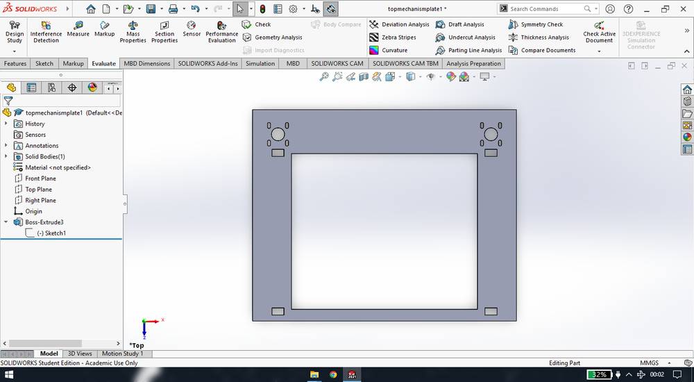
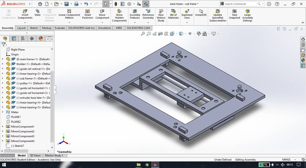
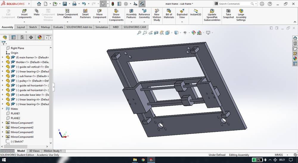
With the constraint of the frame size we had to design the Gantry. The gantry is in three parts, we named them the main frame, sub frame and extruder base plate. The extruder base plate will move on the Y axis and the sub frame will move on the X axis. Kishore Gaikwad designed the main frame by giving them slots for the stepper motor on both ends and gave the slot for the t-holder on which guide rail will be fixed and on that guide rail, we were suppose to move the sub frame on the Y axis.
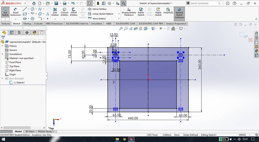
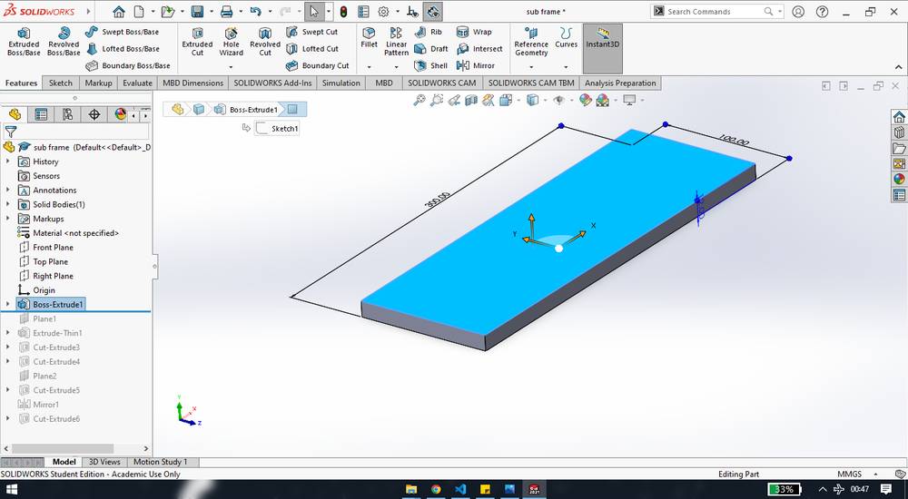
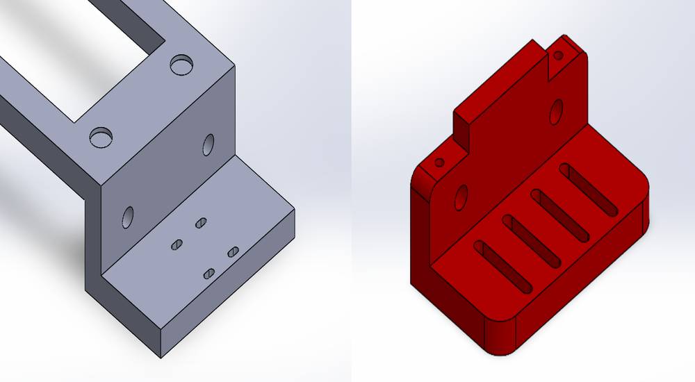
From then on, i was continuing the designing part. I fisrt started working on the sub frame. I was being told that unlike the gantry from the video we saw in the CoreXY website, I had to design the sub frame in a C kind of shape due to less space between the aluminium extrusion frame.
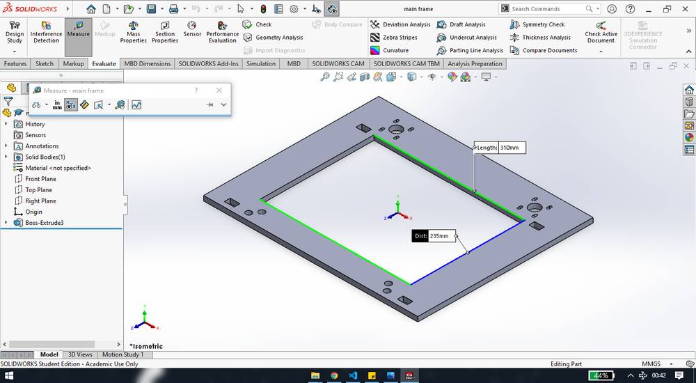
The space between the main frame in which we can move the sub frame was 310mm length and 235mm width.
So i deigned the sub frame with 300mm length(leaving 5mm on both side so the main frame andsub frame don't colide) and 100mm width(i was being told to keep it 100mm),
Then i exturded the L shape onto which we were suppose to mount the linear bearings,
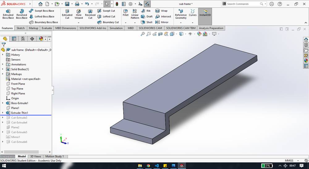
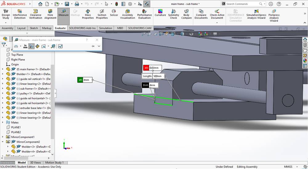
Now the dimension of height and the length of the L shape was arrived after some tentative calculations, however it was later altered after I assembled every part. Like, I took the height and the length a bit large and so the linear bearing was not touching the base of L shape and alos the linear bearing was not on the edge like I intended to do,
So then i measured the distance between the bearing and the base of L shape and made necessary changes.
Then i gave the provision for the idle pulley. The diameter of the pulley we were going to use were 12mm so i gave the provision for the pulley of 12mm too.
The position of the idle pulley had to be tangent to the pulley on the stepper motor. If you see the diagram of the CoreXY mechanism, you'll observe that five pulley on the left and the other five pulley on the right are tangent to each other,
so i gave the same tangent relation between the pulley onto the motor and the idle pulley,
Then i gave the provision of the holes for the linear bearings,
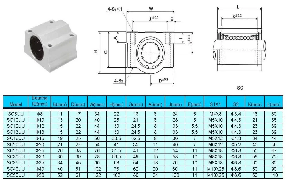
We ordered the linear bearings from https://robu.in/product/sc8uu-8-mm-linear-ball-bearing-slide-unit-cnc-3d-printer/ , so i got the dimensions and position of the holes from their website. Here is the image with the dimensions: https://robu.in/wp-content/uploads/2017/12/NyMLSX-1.jpg
I was being told to make the slot for the holes so that it will be easy while mounting the bearing during the assembling.
then i gave the provision of the holes for the guide rail,
We were suppose to insert the linear bearing onto the guide rail and mount the linear bearing onto the extruder base plate. I miscalculated the position of the holes so the linear bearing was not attached to the extruder base plate
Then i mirror every features on the other side,
Then i made the pocket between which the extruder base plate will move along the X axis,
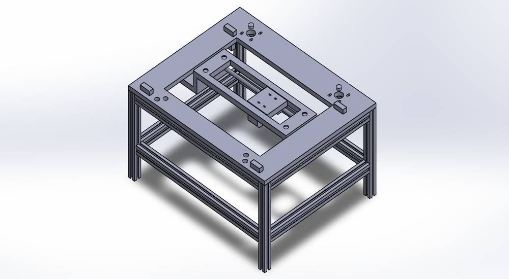
I then downloaded the CAD file of the 20x20x1000mm aluminuium extrusion from Grabcad: https://grabcad.com/library/aluminium-extrusion-20x20-1 to make the assembly of the frame for the gantry and cut into three dimensions that were required ot make the frame: 20x20x200mm, 20x20x320mm and 20x20x400mm,
and then assembled them to make the frame for the gantry,
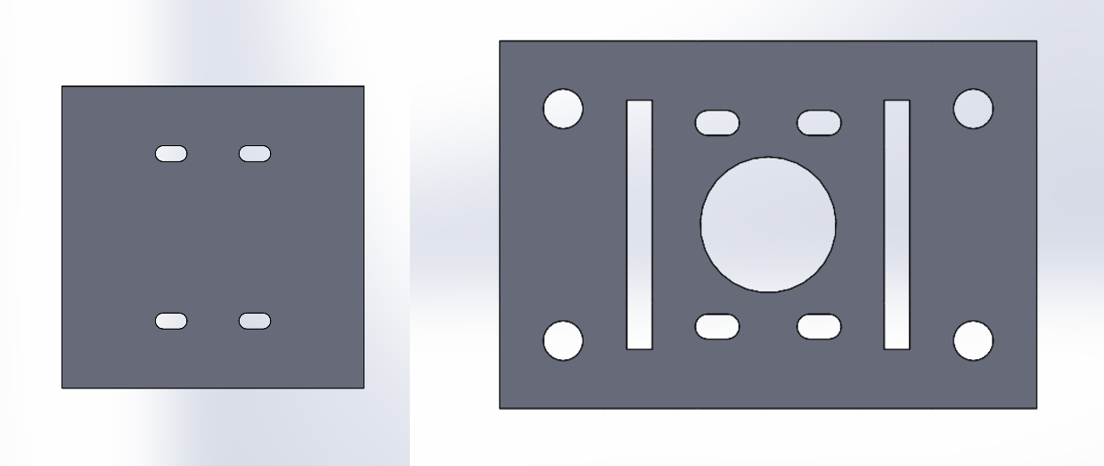
I then designed the extruder base plate onto which we were suppose to mount two linear bearings,
I then designed the guide rail. We had 8mm guide rail in our inventory,
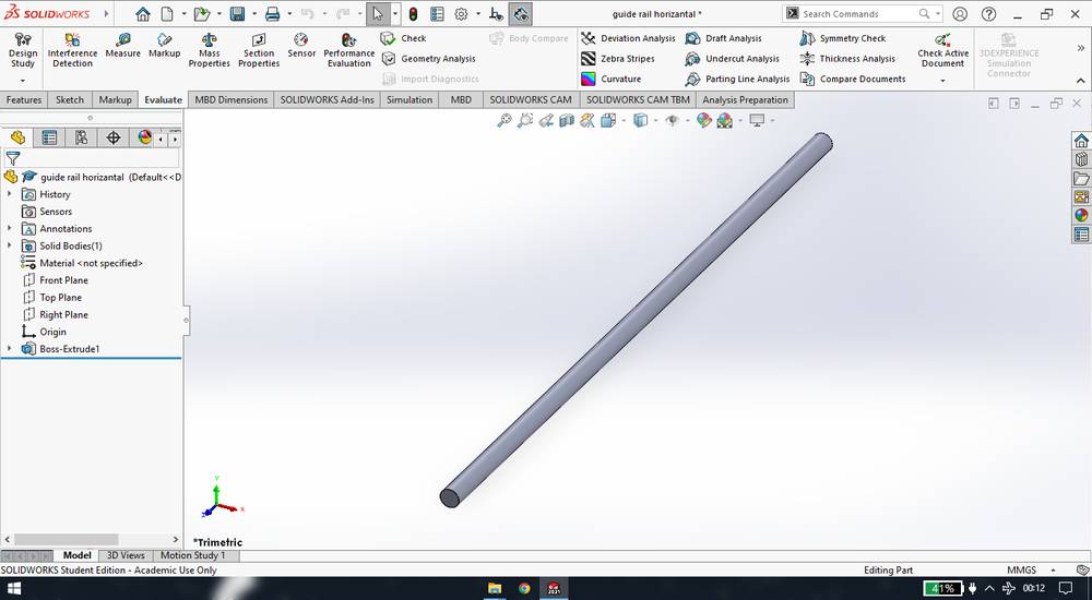
So again the position of the holes for the guide rail had to change later after calculatinmg the distance between the linear bearing and the extruder base plate.
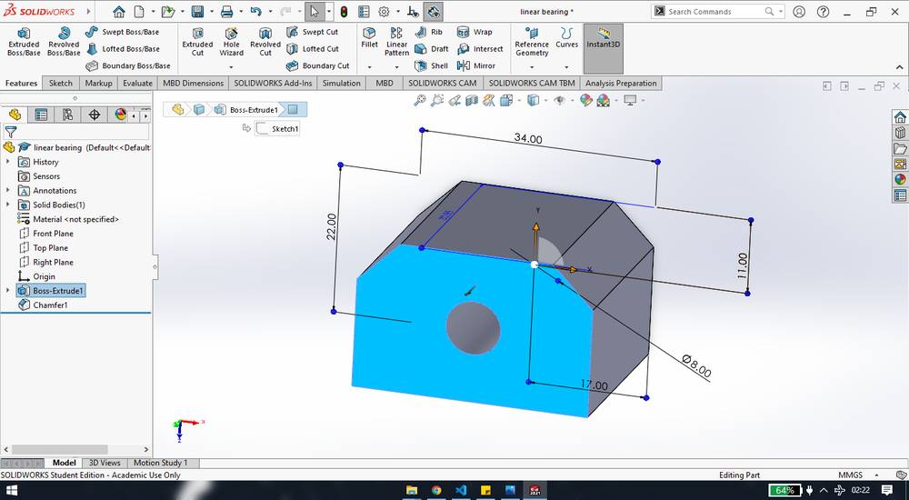
I then designed a linear bearing with the same dimension mentioned in the image i got from the robu.in website: https://robu.in/wp-content/uploads/2017/12/NyMLSX-1.jpg,
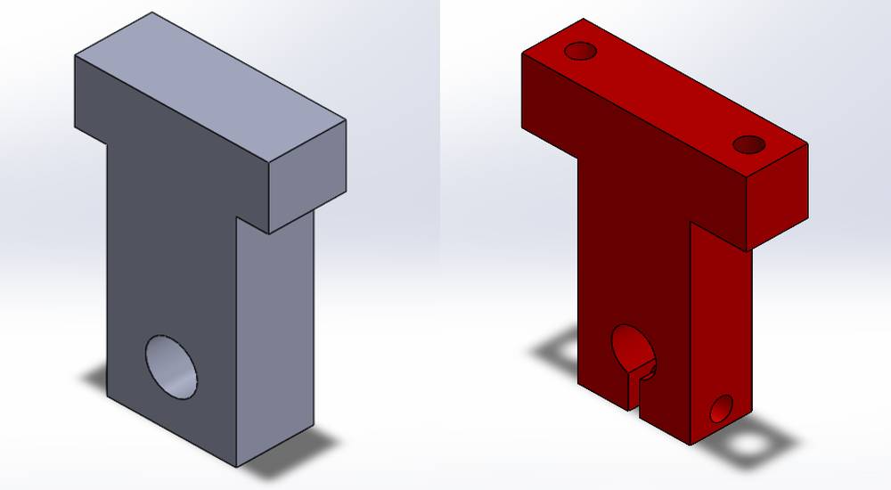
I then designed a t-holder onto which we were suppose to fix the guide rails,
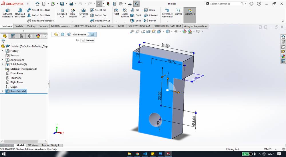
Again the height where the holed are located had to be altered because i made the t-holder a bit longer than required,
After giving few constraints so that the assembly behaves the way i want, like fitting guide rail onto the t-holder, inserting the linear bearing onto the guide rail, mounting the linear bearing onto the sub frame and the extruder base plate, my assembly was ready,

It took me one - one-and-half day to design all the parts and assemble them. Few changes were made later in the design of some parts like,
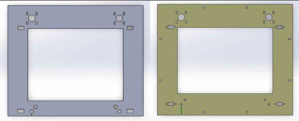
1. I forgot to add holes/slot for mountng the main frame onto the aluminium extrusion frame.
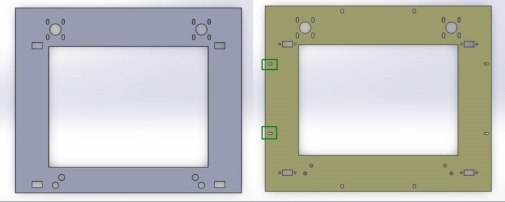
2. I had given the provision for the idle pulley in the main frame and sub frame however we were not suppose to directly attach the pulley onto any frame rather were were suppose to fix a bolt at the places and mount the idle pulley onto the bolt, so the 12mm dianeter hole was changed to 6mmm.
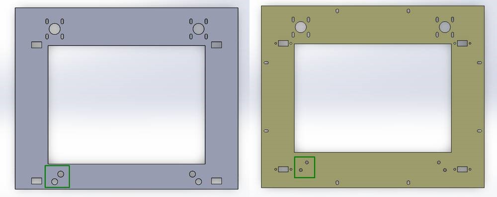
3. I didn't consider the position of the idle pulley with reference to the aluminium extrusion frame, so posiiton of the holes had to be shifted away from the edge because it was being blocked by the aluminium extrusion.
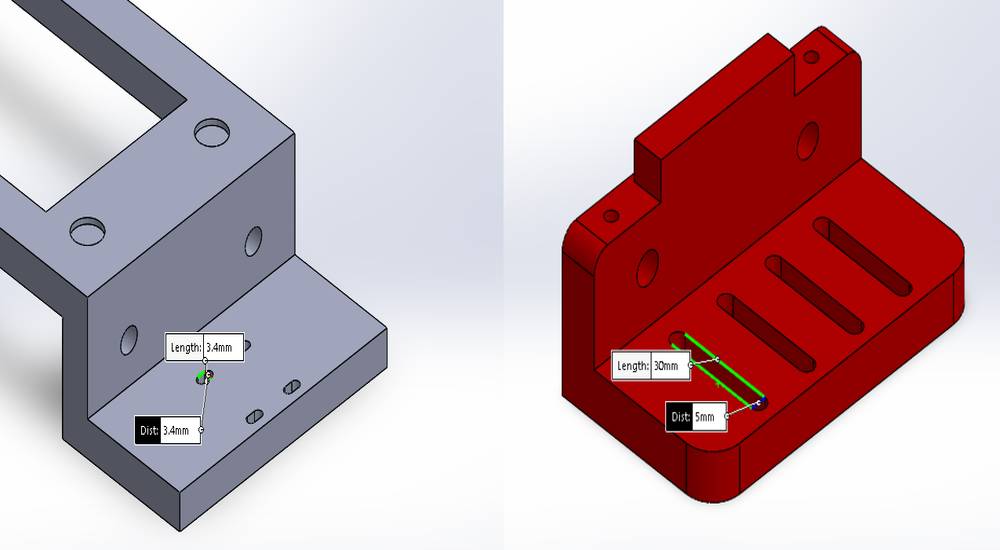
4. Refering to the dimensions of the linear bearing from the robu.in website, i found the size of holes for mounting bearing was 3.4mm and used the same while designing. Now either we didn't had thinner than 3.4mm bolts or i was suppose to give the holes/slot bigger than 3.4mm, the bolts was not going through the holes due to which we had to file them/ drill them down. Later we had to change the dimensions of the slot/holes.
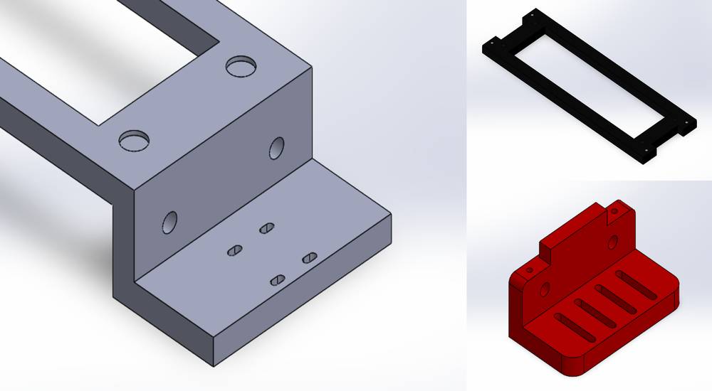
5. I was suppose to make the sub frame into three pieces, the top playe and two plates forming L shape. I thought we can work that out by making/tracing a sketch onto the model rather than re-modeling the whole part and thats what Kishore Gaikwad did, but later the L shape was redesigned and printed onto the 3D pprinter because cutting the sub frame into three parts into the laser cutting machine and then manually sticking the plates with 90° angle was not effective.
6. Both pair of the slots for linear bearing onto the sub frame was merged together for ease in assembly.
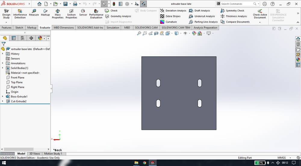
7. Provision for 4 holes were given onto the extruder base plate for mounting the bolts onto which we were suppose to fix the end of both timing belt. Provision for 1 hole was given for the syringe to pass through. To fix the syringe we manually drilled the hole onto the extruder base plate. Provision of 2 more slot were given to mount the walls of extruder.
8. Changed the design of the t-holder. Had to give the provision for the holes to fix the t-holder on the main frame too.
Maor of the changes in the Gantry was made by Kishore Gaikwad and the designing/changing the parts related to the extruder was done by Kiran Wakchaure.
Assembling
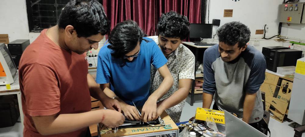
So after designing, I was participating in assembling of the machine. It took a few days to assemble and re-assemble the parts until the machine
was working. I'll try to mention everyting that was going on from April 07, the start of the make a machine week.
Day-1 | April-07
We had orientation in the morning where we decided to make the machine with the CoreXY mechanism, until then we just had decided to make the
conductive ink printer. On this day we were divided into groups and assigned task between groups like designing gantry, programming, designing
extruder and making the conductive ink. Between me and Kishore Gaikwad, we had the responsibilty to design the Gantry of the machine.
After the task were assigned, we were looking for all the parts that were available in our inventory. We already had the aluminium extrusions,
guide rail, aluminium plate for the bed, stepper motors, RAMPS 1.4 shield, Arduino Mega and the power supply.
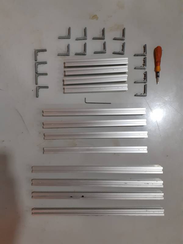
We had in our inventory two 20x20x200 aluminium extrusion and one 20x20x600(which we dismantle it from the previous student project and I am sure
next year students are going to dismantle our machine and use the componments for their project.)
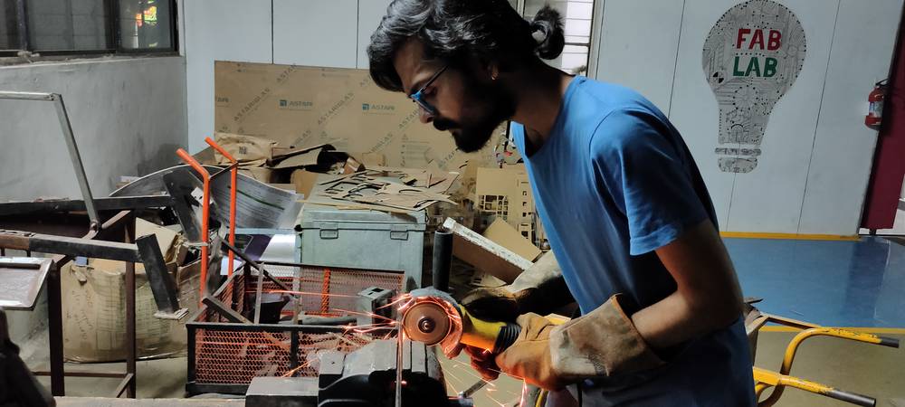
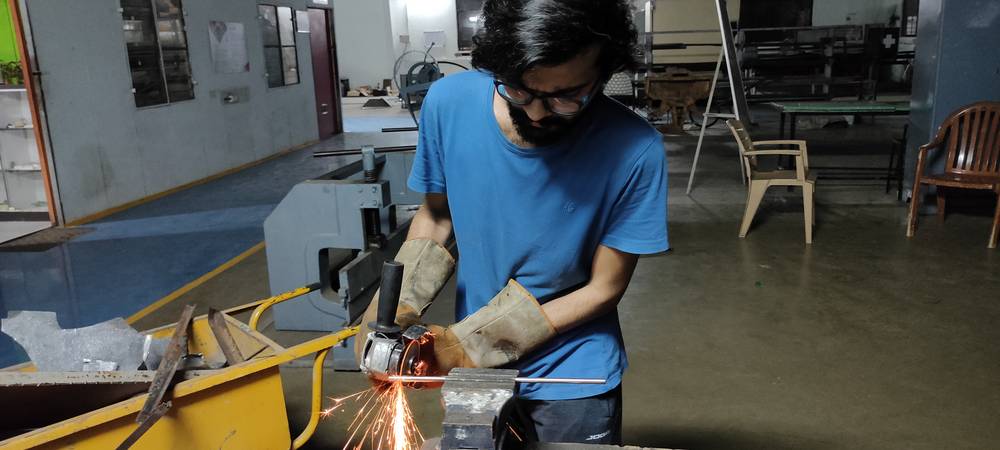
so we had to cut the 20x20x600 in order to fulfil our requirement of
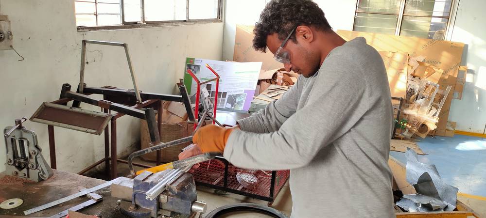
four 20x20x200 aluminuum extrusion. So here is me and Kishore Gaikwad marking the aluminium extrusion,
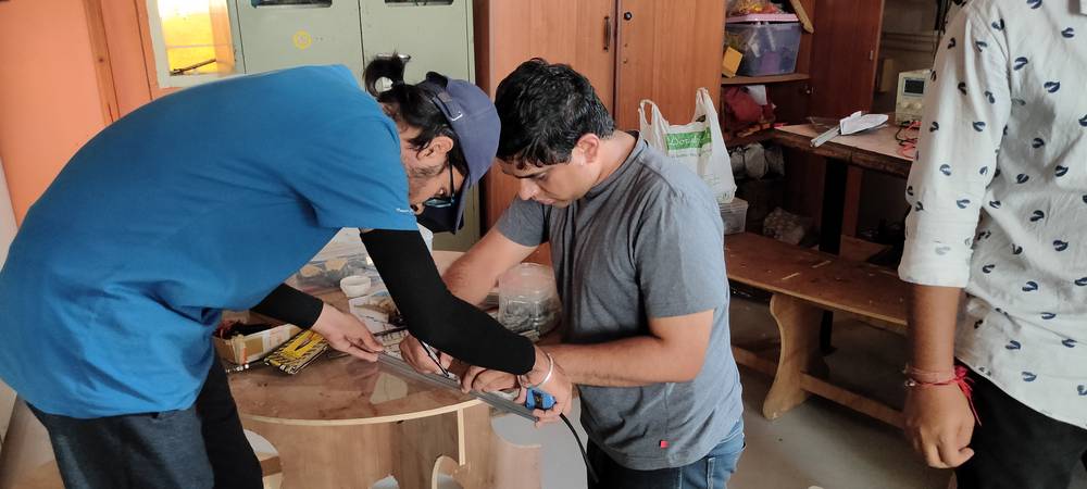
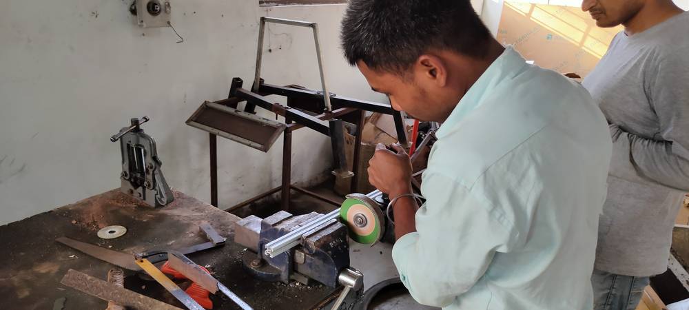
Here is Kiran Wakchaure attempting to cut the aluminuim extrusion,
later we had to take help from the felow student from DBRT at Vigyan Ashram,
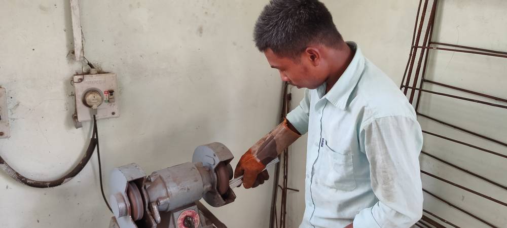
AFter that our set of aluminium extrusion was ready,
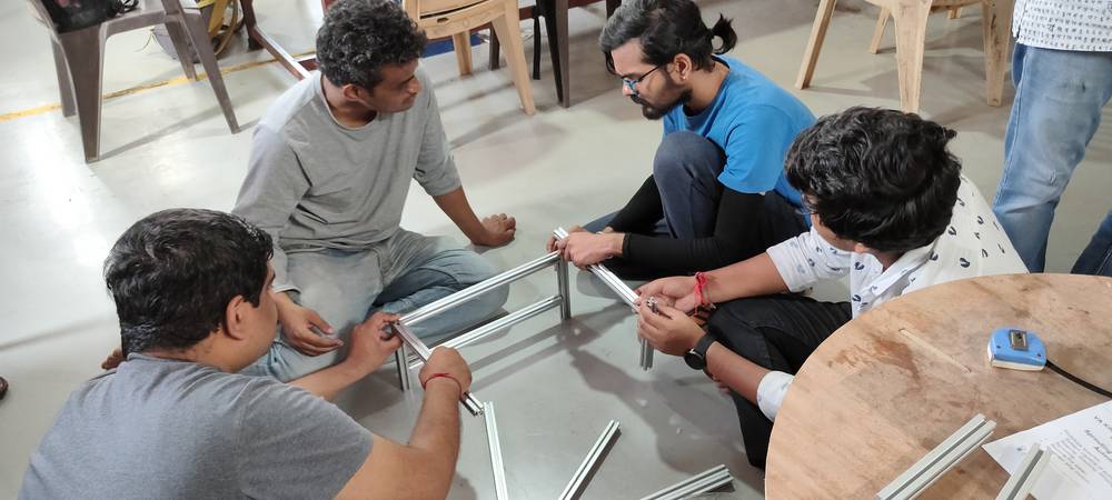
Later we started the assembly of the aluminium extrusion frame,
At the end of the day, I started the designing of the Gantry by the timei completed 30-40% of the Gantry, it was six in the morning so i decided
to continue the design the next day(same day, technically)
Day-2 | April-08
This whole day went into completeing the design of the Gantry. I have mentioned the description of the designing in detail above.
Day-3 | April-09
With the design ready, we cut them into cardboard to see if there is any obvious change needed to make,
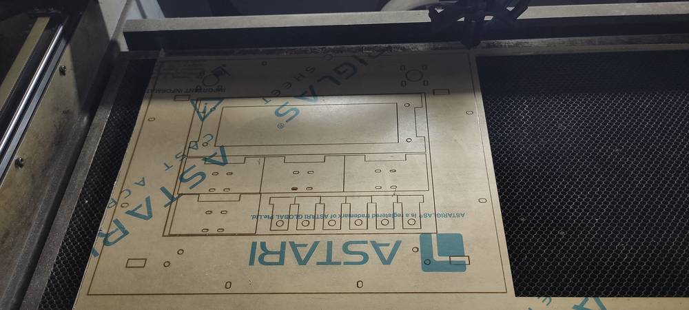
after confirming that the design was fine, we cut them with Acrylic sheet into laser cutting machine.
The guide rail we had in our inventory was a bit longer so we had to cut them too,
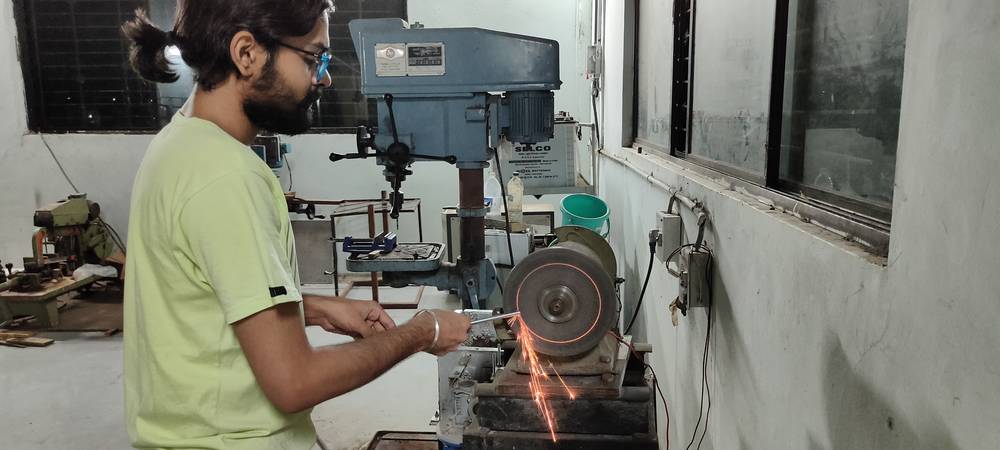
The acrylic sheet we had in our inventory was 5mm thick so we cut two pieces of every part and them stuck them with fevikwik. A few times
when there was misalignment after sticking the trwo acrylic parts, we had to again file the holes down in order to insert the guide rail
properly. It was already midnight so we called it a day. (((instructor gathering on this day)))
Day-4 | April-10
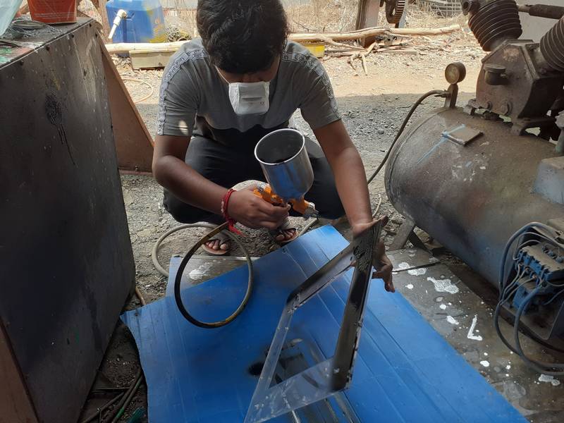
with the acrylic sheets glued together, Jaydeep Parejiya spray painted them with black color,
The width of the slot for the t-holder was 10mm considering we were going to stick two 5mm acrylic piece, but when we tried to fit them, the
t-holder was loose. So we had to cut them in 11mm sheet, which is much thicker than 10mm, so i had to sand/grind the t-holder in order to fit into
the main frame. Later changes was made in the design.
It was this day that our linear bearing arrived that we had ordered earlier.
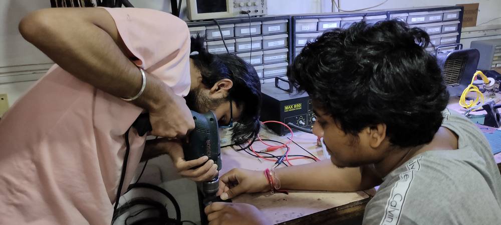
As mentioned above, the holes for mounting the linear bearing were either too short or we didn't had the thinner bolt in the inventory at that
time, so we had to file/drill them. Initially we were using the file to make the hole bigger but that was a very tedious job, so then we
started using drill machine. We were having difficulty inserting the guide rail onto the t-holder so we had to file the holes of t-holder too.
Later we changed the design of t-holder.
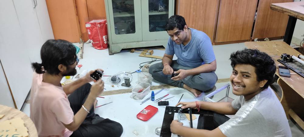
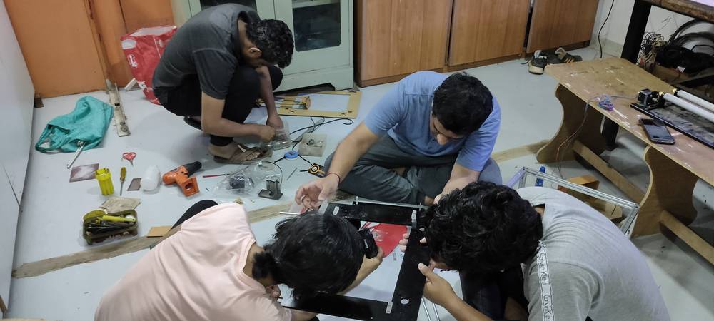
With every part ready, we started the assembly,
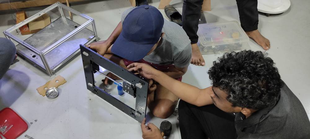
we were having difficulty moving the sub frame onto the guide rail along the Y axis. The movement was not smooth. It was concluded that the t-holder
i had sanded/grinded was not even so it was wobbling onto the frame. The L shape that we stick to make the sub-frame was not a proper 90°.
So we cut the new main frame with bigger t-holder slot of 11mm with 5mm
acrylic sheet and cut new t-holder with 11mm arcylic sheet.
We were having a lot of difficulty with the laser cutting machine, because it was not consistent at all. Here is the preview of t-holder with 8mm
hole onto the guide rail,
Note that earlier when we were filing the holes down because it was too tight, that was 8mm too. After cutting the t-holder with 8mm, 8.1mm, 8.2mm
holes, we were back to keeping the t-holder with 8mm holes.
After the t-hoder and the new main frame was cut, we call it a day since it was already 4:30 in the morining.
((( it was today Kiran bhai brought the pulley, timing belt, and bolts of rmounting the linear bearing)))
Day-5 | April-11
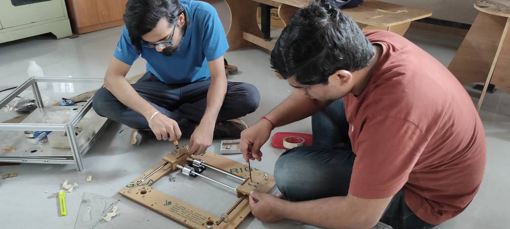
We again started the assembly with newly cut main frame and t-holder.
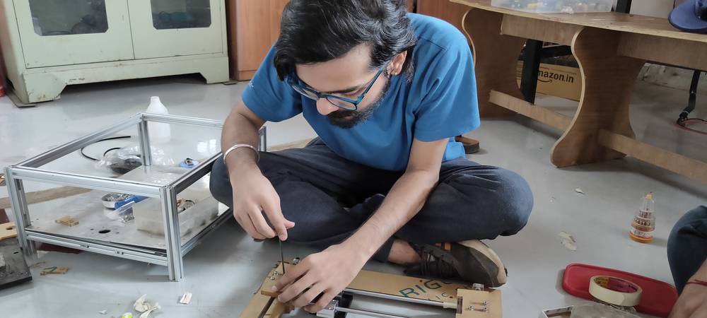
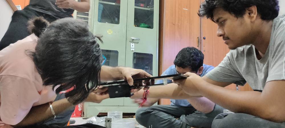
This time we assembled the parts a bit differently. After observing that the movement of the subframe was still not smooth along the Y-axis,
i suggested that instead of fixing the linear bearing first and then mount the whole sub frame onto the guide rail, why not try to first
mount the linear bearing onto the guide rail first and then fix the sub frame onto the linear bearing later? So here we are trying that to see
if this has any impact,
This surely made some improvement in the movement of the sub frame but there were still a lot of changes to be made.
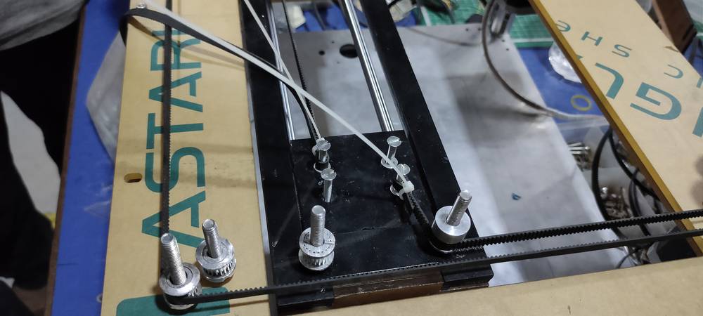
The t-holder was still wobbling a bit, so we decided to stick them onto the main frame with hot glue,
When we tested the mvement of sub frame again, the guide rail was moving along the sub frame when in actual the guide rail is suppose to be fixed
onto the t-holder. So Jaydeep Parejiya suggested to set the guide rail so that the 15mm of the guide rail will stick out on both end of the t-holder
(the dimention of the guide rail was 30mm bigger than the distance between the two t-holder). He did that by sticking masking tape onto both
of the guide rails. From what i think, the size and position of the guide rail doesn't matter as long as both end of the guide rail is fixed
by the t-holder. What actually was happening was that when we move the sub frame, the guide rail was sliding along too resulting into diaginal
movement along the Y axis. So after sticking the masking tape, the movement of the guide rail along the sub frame was restricted and i guess that
was something that contributed inb the smooth movement of the sub frame.
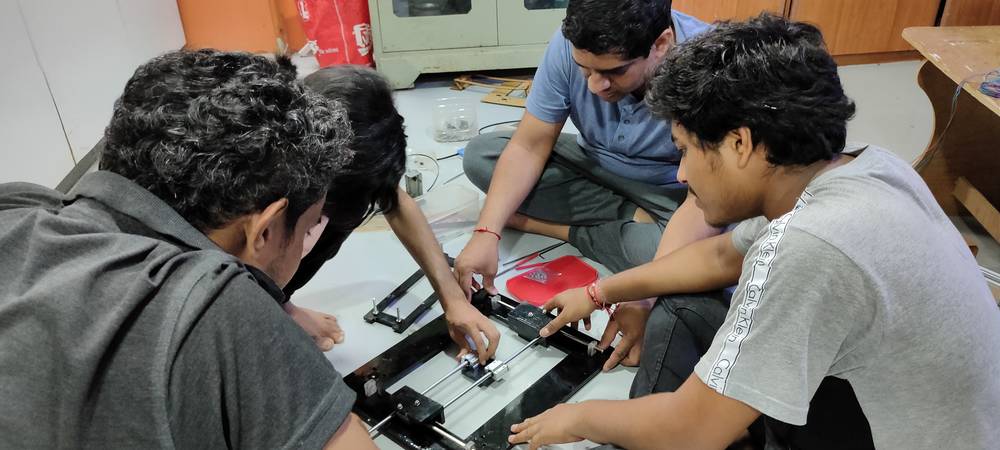
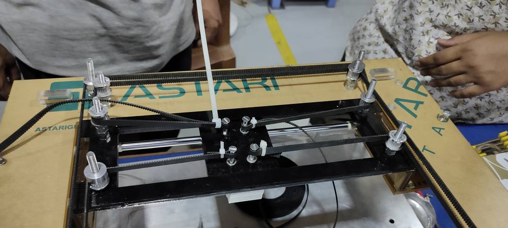
After making all these changes in the assembly there was sure a huge change in the movement of the sub frame. The movement was now a lot smoother than earlier,
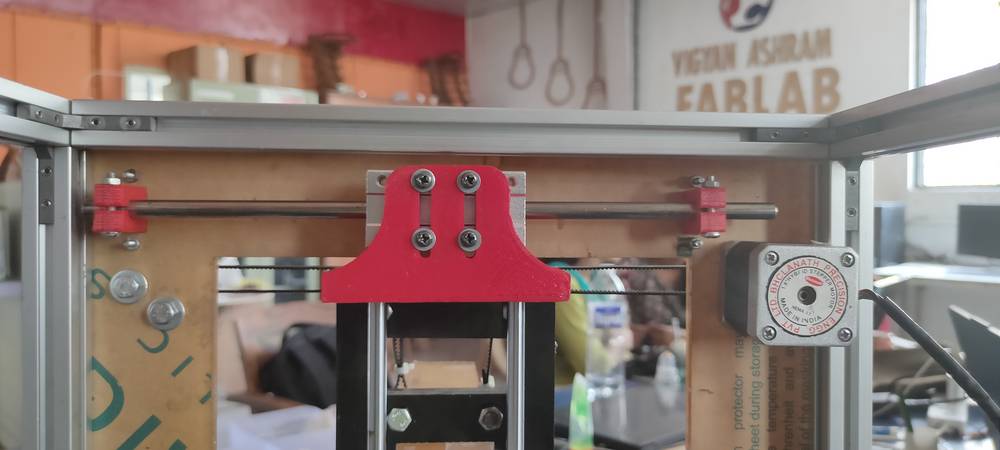
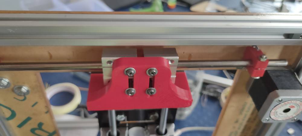
We then mounted the stepper motor and pulley onto the Gantry. After setting different height for two sets of pulley, we started mounting
timing belt onto the pulley,
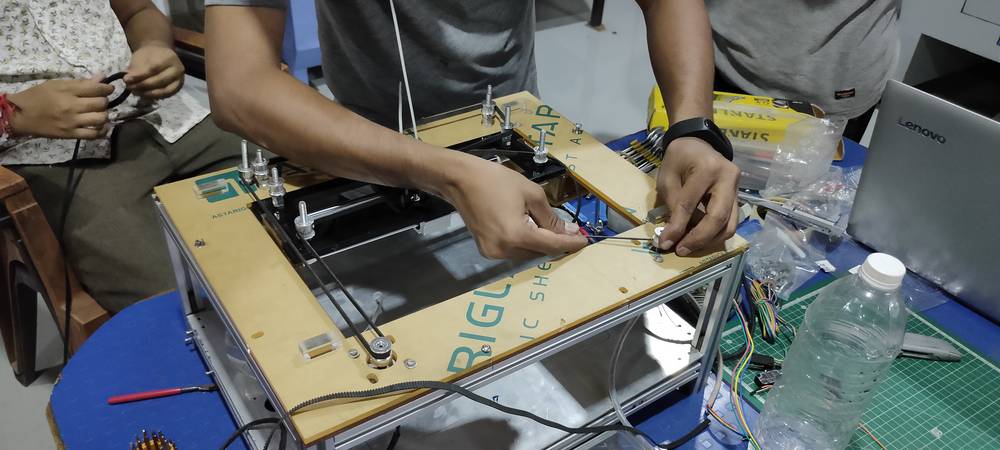
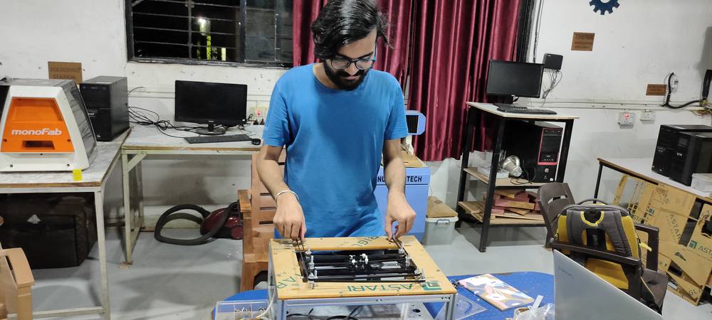
After everythng was set we tried the manual actuation to see if the if we can move the sub frame and extrusion base plate by just rotating the
pulley manually, and here is the result:
It was already midnight so we decided that we'll test the Gantry by rotating the pulley with the help of the motor(automatic actuation) and
call it a day
Day-6 | April-12
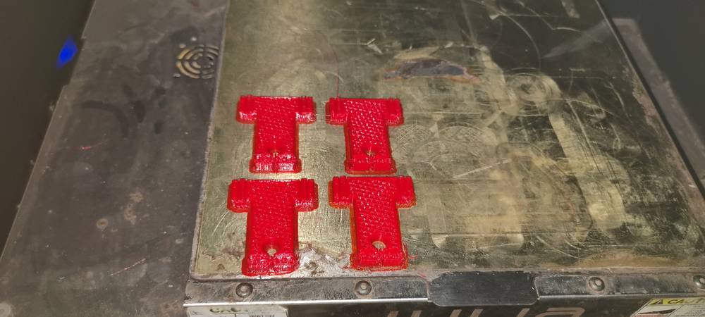
The other day (Day-5) when we were facing the issue with the movement of sub frame even after cutting the new frame and t-holder, few of my
colleagues decided to start printing the L shape of the sub frame into 3D printer since the L shape of the sub frame was still not at a
perfect 90° angle.
As decided, we were suppose to test the automatic actuation of the Gantry with the help of motor, Devesh Nair tested and I was being told (i was
not in the lab at the timme of testing) that due to some reason, the movement of the sub frame and the extruder base plate was very jerky, complete
opposite of what i anticipated. I thought that manually rotating the pulley can still have some room for error my motors can't have any error.
Unfortunately, they didn't record the result of the automatic actuation done by motors, so i do not have anything to show here.
So with the L shape printed, we replaced the acrylic L shape with the 3D printed L shape.
Along with the assembly of the Gantry, Kiran Wakchaure was designing the extrude case and we were testing that in our assembly,
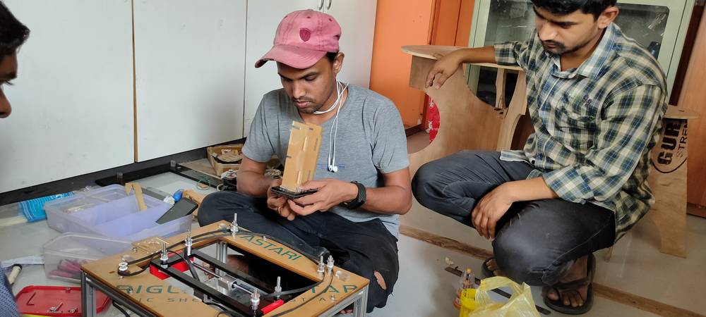
The t-holder was still not very reliable for preveting the guide rail from sliding, Kiran Wakchaure decided model and print new t-holder,
where we can fix the t-holder onto the main frame and also fix the guide rail with the help of bolt and nut.
Now the 3D printer too was giving us trouble by printing only 50% of the model and finishing the printing,
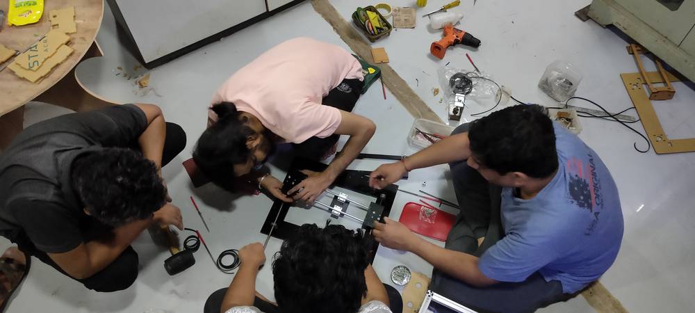
Even after attaching the 3D printed L shape, the movement of the sub frame was not reliable enough. So it was decided to use two linear bearings
(instead of one) on both sides of the sub frame. We didn't had any extra linear bearing so we temporarily took those two linear bearing
from the extrudr base plate and attached to the sub frame to test if it would make things any better,
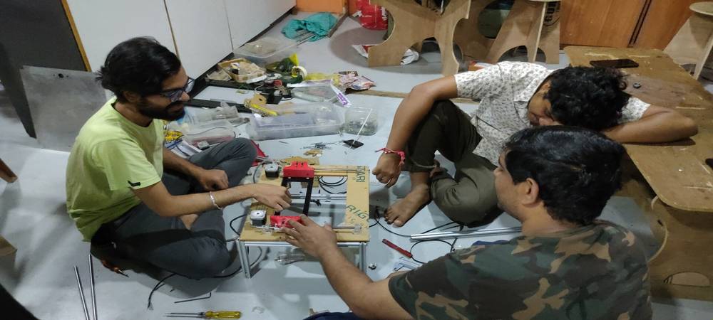
after attaching two linear bearing, there was a drastic chage in the movement of the sub frame. More than smooth, the movement became
very stable,
It was already midnight and with new t-holder in print and no extra linear bearing for the extruder base plate we decided to purchase new
linear bearing and continue the assemble later and called it a day.
Day-7 | April-13
With the new t-holder printed and two linear bearing on both end of the sub frame attached(((kishore bhai bought the linear bearing))),
the machine was ready for the final test.
and it did pass with the flying colors,
<<<---MANUAL ACTUATION--->>>
<<<---AUTOMATIC ACTUATION--->>>
It took the rest of the day and the next day for Devesh Nair and Vrushabh Zunjunkar to setup limit switch and configure the machine with the
marlin firmware so that it behaves the way we want.
Day-9 | April-15
We had to print a lot of circuits and do a lots of trial and error with making the conductive ink, sometimes the ink would become very thick and
it woun't extrude from the syringe and sometimes it would be very thin and would do a messy print.
Finally this is the result of the machine fully functioning by printing a simple circuit by extruding the conductive ink,
Here you'll find all the design files that i made in solidworks: design files
Group Assignment
link for the page of group assignment: https://fabacademy.org/2022/labs/vigyanashram/machine.html
Link for all my colleague's webpage:
Devesh Nair: https://fabacademy.org/2022/labs/vigyanashram/students/deveshs-nair/
Jaydeep Parejiya: https://fabacademy.org/2022/labs/vigyanashram/students/jaydeep-parejiya/
Kiran Wakchaure: https://fabacademy.org/2022/labs/vigyanashram/students/kiran-wakchaure/
kishor Gaikwad: https://fabacademy.org/2022/labs/vigyanashram/students/kishor-gaikwad/
Vrushabh Zunjunkar: https://fabacademy.org/2022/labs/vigyanashram/students/kishor-gaikwad/
Ashish Shende: https://in.linkedin.com/in/ashish-shende-designs?original_referer=https%3A%2F%2Fwww.bing.com%2F
Drip Irritation by Fenil Chandarana is licensed under Attribution-NonCommercial-NoDerivatives 4.0 International![]()
![]()
![]()
![]()